Meters and gauges
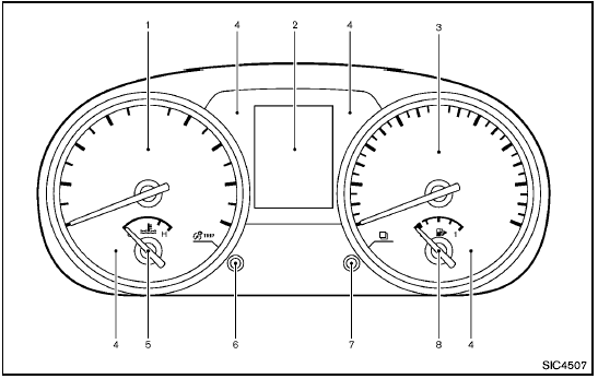
Meters and gauges
1. Tachometer
2. Vehicle information display
3. Speedometer
4. Warning/indicator lights
5. Engine coolant temperature gauge
6.  switch (twin trip odometer control
and brightness control)
7.  switch (settings control and trip
computer control)
8. Fuel gauge
The needle indicators may move slightly after the ignition switch is turned to the LOCK position. This is not a malfunction.
Speedometer
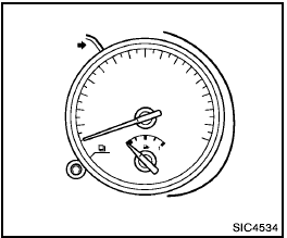
Speedometer
The speedometer indicates vehicle speed in miles per hour (MPH) or kilometers per hour (km/h).
Odometer/twin trip odometer
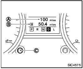
The odometer and twin trip odometer are displayed on the vehicle information display when the ignition switch is in the ON position.
Odometer
The odometer A records the total distance the vehicle has been driven.
Twin trip odometer
The twin trip odometer B records the distance of 2 individual trips (TRIP A and TRIP B).
Changing the display:
Briefly push the  switch C
to change the display as follows.
TRIP A  TRIP B
 TRIP A
Resetting the trip odometer:
Push and hold the  switch for approximately
1 second to reset the selected trip (TRIP A or TRIP B).
Tachometer
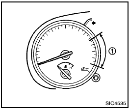
The tachometer indicates engine speed in revolutions per minute (RPM). Do not rev the engine into the red zone 1 .

When engine speed approaches the red zone, shift to a higher gear or reduce engine speed. Operating the engine in the red zone may cause serious engine damage.
Engine coolant temperature gauge
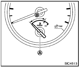
The gauge A indicates the engine coolant temperature.
The engine coolant temperature is within the normal range when the gauge is within the zone B shown in the illustration.
The engine coolant temperature varies with the outside air temperature and driving conditions.

If the gauge indicates engine coolant temperature near the hot (H) end of the normal range, reduce vehicle speed to decrease temperature. If the gauge is over the normal range, stop the vehicle as soon as safely possible. If the engine is overheated, continued operation of the vehicle may seriously damage the engine. See “If your vehicle overheats” in the “6. In case of emergency” section for immediate action required.
Fuel gauge
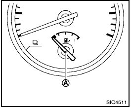
The gauge A indicates the approximate fuel level in the tank.
The gauge may move slightly during braking, turning, acceleration, or going up or down hills.
Refill the fuel tank before the gauge registers 0.
The low fuel warning light  illuminates
and low fuel warning appears on the vehicle information display when the fuel tank
is getting low. Refuel as soon as it is convenient, preferably before the gauge
reaches the empty (0) position. There is a small reserve of fuel in the tank when
the fuel gauge reaches the empty (0) position.
The  indicates that the fuel-filler
door is located on the passenger’s side of the vehicle.

- If the vehicle runs out of fuel, the
 malfunction indicator light (MIL) may
come on. Refuel as soon as possible. After a few driving trips, the
 light should turn off. If the light
remains on after a few driving trips, have the vehicle inspected by a NISSAN dealer.
- For additional information, see “Malfunction Indicator Light (MIL)” later in this section.
Instrument brightness control
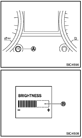
The instrument brightness control operates when the headlight switch is in the
 or
or
 position.
Turn the control A to adjust the brightness of the meter panel and the instrument panel lights.
The brightness indicator B will be shown briefly in the vehicle information display when the control is turned.
When the brightness level reaches the maximum or minimum, a beep will sound.
When the brightness level reaches the minimum, the meter panel and the instrument panel lights will be turned off.
After the ignition switch is turned to the OFF position, the brightness indicator B is displayed for 30 seconds.
See also:
Heater and air conditioner
WARNING
• The air conditioner cooling function
operates only when the engine is
running.
• Do not leave children or adults who
would normally require the support
of others alone in your vehi ...
Injured persons
NISSAN recommends that injured persons use
seat belts. Check with your doctor for specific
recommendations. ...
Hood
- Make sure the hood is completely closed and latched before driving.
Failure to do so could cause the hood to fly open and result in an accident.
- If you see steam or smoke coming from the engin ...
