Meters and gauges
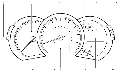
1. Instrument brightness control switch
2. Tachometer
3. Speedometer
4. Fuel gauge
5. Warning/indicator lights
6. Trip computer switch
7. Dot matrix liquid crystal display
— Trip computer
8. Engine coolant temperature gauge
9. Odometer/twin trip odometer/Continuously Variable
Transmission (CVT) position indicator
10. RESET switch for trip odometer
The needle indicators may move slightly after the ignition switch is pushed to the LOCK position. This is not a malfunction.
CAUTION
• For cleaning, use a soft cloth, dampened with water. Never use a rough cloth, alcohol, benzine, thinner or any kind of solvent or paper towel with a chemical cleaning agent.
They will scratch or cause discoloration
to the lens.
• Do not spray any
liquid such as
water on the meter lens. Spraying
liquid may cause the system to
malfunction.
See also:
Maintenance precautions
When performing any inspection or maintenance work on your vehicle, always take
care to prevent serious accidental injury to yourself or damage to the vehicle.
The following are general precaution ...
Exterior front
Exterior front
1. Front view camera*
2. Hood
3. Headlight and turn signal lights
— Switch operation
— Bulb replacement
4. Windshield wiper and washer
— Switch operation
— Blade repla ...
Digital Versatile Disc (DVD) Player Operation (models with Navigation
System)
Precautions
Start the engine when using the DVD entertainment
system.
Movies will not be shown on the front display
while the vehicle is in any drive position to reduce
driver distraction. Audi ...